I/O Controller
The I/O controller is really the physical heart of the project. It comprises the following parts:- Arduino Due I/O processor
- Printed circuit board
- VFO encoder(s)
- Rotary encoder(s)
- Switch multiplexers
- Pushbutton switches
- VFO control LED pushbuttons
- Optional 800x480 pixel display
Circuit diagram
Following is the generic circuit diagram for the I/O controller. This is (I think) the largest configuration that anyone is likely to ever want to build. Smaller controllers will be a subset of this circuit, with fewer controls but the general layout and, importantly, the pin-outs will remain the same. |
| The Mk II Maxi Controller circuit diagram |
Arduino pin-out

Each VFO encoder and rotary encoder provides two outputs with quadrature data that permits the I/O controller to determine the direction of rotation and the number of steps the control has been turned. Encoder connections to the Arduino use up most of the pins we need and the pin-out of the Due places a natural but not unreasonable limit on the number of these controls.
One of the things we all want to do quite frequently is to switch between VFOs, go split and generally manage what VFO is performing any given function. I rather like the Yaesu way of doing this, with an Rx and Tx illuminated pushbutton for each VFO. With these you can go split, revert to simplex and mute receivers all with single button presses. The associated LED displays the current status.
It will come as no surprise that I have implemented this concept in my Flex controller. It's also interesting to note that the FlexRadio Maestro has followed this concept, albeit in a very slightly different way, so it must be a winner! The switches are simply routed to pins on the switch multiplexers and as you can see on the pin-out diagram, four output pins, 26..29, provide the LED drive outputs.
Switch multiplexer
 |
| The switch multiplexer |
The multiplexer has four addressing inputs that are scanned by pins 30..33 on the I/O processor from 0000 to 1111 over a 16ms period (16 steps, one step per ms). The multiplexed input line from the multiplexer contains the switch setting (on or off) for the current address time slot.
You can find the switch multiplexer at http://tinyurl.com/htvnr35 and lots of other places.
PCB
It is, of course, possible to construct the controller without a PCB, just using point to point wiring. Possible, but not particularly satisfactory. The PCB approach brings many benefits:- Virtually no wiring. Just the VFO encoders and the LED pushbuttons need wiring up
- Switches, encoders and the LCD are all mounted on the PCB
- The Arduino is "piggybacked" onto the PCB, greatly reducing interconnect wiring
- The PCB directly attaches to the front panel for a really neat build
I/O processor
The I/O processor is an Arduino Due. This is actually quite a powerful processor, based on the ARM Cortex M3 but it is inexpensive and does the job admirably. The main advantage of the Arduino platform is that it is ubiquitous and very easy to work with. All the software development tools are free of charge and it is a simple process to load the I/O processor code, compile it and upload it to the Arduino.
The Arduino Mega will not work in this application because it has too few interrupt-capable pins. Smaller Arduinos have insufficient I/O connectivity for this application.
There are lots of "Chinese copies" of Arduino out there, most of which claim full compatibility with the original. I've not tried any of them but I have no particular reason to suppose that they will not work. Try them if you will and let me know what happens.
You can get the Arduino Due from loads of places but RS Components has them in stock right now at a good price and as you'll probably be buying other stuff from there for the controller it makes sense to consider that source, at least for UK-based builders. http://tinyurl.com/jpsw9xm
VFO encoders
Every project will have one or two VFO encoders and it pays to spend a bit of time selecting the right component for the job. Personally, I like a very free spinning VFO knob and therefore I favour high speed rotary encoders that are typically used in industrial control applications and have resolutions in the 400 to 800 steps/revolution range. If you prefer a little more friction then you can get encoders that are designed for hand use although they tend to be lower resolution, around 200 steps/revolution.
One can spend an awful lot of money on high resolution rotary encoders but there is in fact no need to. There are numerous suppliers, mainly in the Far East that sell perfectly acceptable 200 to 600 steps/revolution optical encoders costing in the region of £10 per unit. Ebay is a good place to explore.
The original Mk I controller was designed using 400 step encoders but I am using 600 step encoders for the Mk II because that was what I could easily source at the time. Anything over 200 steps/revolution will do and the software can scale the actual tuning rate as required.
http://tinyurl.com/gm64lmc should get you started.
Rotary encoders
Rotary encoders are commonplace cheap components these days on account of their ubiquity in so much electronics.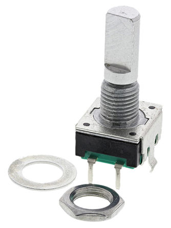 My PCB designs anticipate the use of Bourns mechanical encoders, which are readily available from RS Components and other outlets for around £1.50 each. These are 24 step/revolution units and incorporate a push-switch, which is handy for our application.
There are numerous options to consider, mainly associated with shaft construction and length. I find it easier to find the right sort of knobs for the standard flat 6mm shaft and 20mm shaft length is about right for the knobs to be nicely spaced from the front panel.
http://tinyurl.com/gmxbkr7 is a good starting point.
Switches
There are literally thousands of options for pushbutton switches but one has to start somewhere and, in due course, design a PCB around a particular type of switch.
I've settled on the Taiwan Alpha SK1203001024SNB3 D6 Square Black Keyboard Switch.
They are compact and easily mounted on the PCB. They can be placed quite close to one-another and present a tidy appearance in rows of four or so. You can get them in several colours as well if you wish and they are very inexpensive.
They are compact and easily mounted on the PCB. They can be placed quite close to one-another and present a tidy appearance in rows of four or so. You can get them in several colours as well if you wish and they are very inexpensive.
There are plenty of other pushbutton switches that fit into a 0.2" matrix PCB pad.
Available from Rapid Electronics: http://tinyurl.com/jj6muat
Available from Rapid Electronics: http://tinyurl.com/jj6muat
LCD
It was rather more difficult to find a suitable display for the controller than I was expecting. The requirement is an 800 x 480 pixel display in a 5" diagonal profile. It seems illogical these days to go for any other connection than HDMI. I've ended up with the Adafruit 5" touch-screen unit, which is reasonably priced and fairly readily available. I suspect that other options will emerge as time goes on.
I have not found the touch-screen facility particularly useful. It's obviously designed to be used in a single display environment and that's probably not how it will be used in the controller.
The problem is that that touch feature is effectively just another mouse click to the host PC, so wherever your main mouse happens to be, that's what the touch operates. Fortunately not really a problem - touch-screen isn't really very useful in this application.
Available from ModMyPi: http://tinyurl.com/znvqv9t
HDMI connector

This is effectively just a 12" HDMI extension lead but it should be easy to route that to the back panel of your controller, or directly to the Host processor if that is co-located. It can be obtained on the slow boat (and it is slow!) from here http://tinyurl.com/jap7kd9
VFO LED pushbutton
I searched high and low to find small LED pushbutton switches but I think these from RS components meet my needs. They are inexpensive and simply push into the front panel, using very little space. Unfortunately, you do have to solder some short lengths of wire onto the component, which is fiddly, for onward connection to a PCB header.
http://tinyurl.com/hsz6az6 for the green LED
http://tinyurl.com/huxr3us for the red one
Host Controller
Hardware for the host controller is far more flexible. In essence any Windows-based platform should suffice. Whatever you use, it will need at least the following features:
- Spare USB socket for connection to the I/O controller
- Network connection, ideally wired but WiFi is OK for laptops and other portable solutions
- Support of two or more displays
Most, if not all controller applications will run Smart SDR on the PC. This provides the waterfall/panadapter features and it does such a good job that I see no point in adding this functionality to my controller. The controller works perfectly alongside Smart SDR. I anticipate that you will want a large display for that and a separate 800x480 pixel display for the controller.
I have run the host controller on laptops, desktops and single board windows computers. All work just fine.
No comments:
Post a Comment